

|
|
|
|
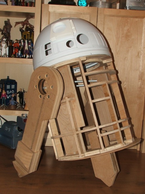
11th October 2009 The edges of the legs were quite rough, and I needed to fill some some holes I had made previously - using P38 car filler I filled and sanded the edges of both legs, the horseshoes, and filled in the holes. I've been buying lots of resin details for the legs from Marco at R2 Builders Club Parts and Keith at www.resinparts.com - including the shoulder hubs, buttons, & hydraulics, the leg hydraulics & booster covers, the ankle cylinder wedges and the curved sections of the ankles. The resin curved sections are doweled & glued in place and everything else has wooden dowels aligned to holes which will be glued once they are painted. It's nice to see the legs finished apart from paint... |
|
|
|
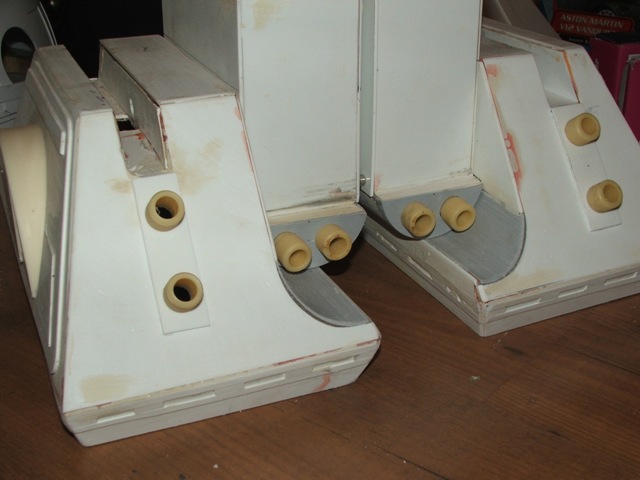
27th September 2009 - pt 1 I picked up some resin knurled hose fittings off Don Jarr's shop on eBay a few weeks back - bargain at £2 plus postage - and this morning drilled some pilot holes and sanded them out so the resin hose ends fitted snugly. I've also test fitted the battery box harnesses I got from Marco R2 Builders Club Parts - again really good parts and fit perfectly. The (3) feet & battery boxes are now ready to be painted.... |
|
|
|
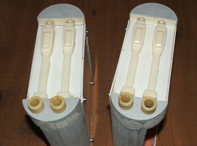
27th September 2009 - pt 2 The box from Marco at R2 Builders Club Parts also contained a pair of resin booster covers and leg struts. Fitting these was a doddle - first I made some ankle bracelets from 2mm styrene sheet so the covers are spaced correctly. Two holes were drilled in the booster covers - one underside centre top and the other in the very bottom opposite side to the channel in the leg that the wires will run down. Matching holes were drilled in the leg and a wooden dowel was used in both holes to cite the cover. Once painted, a small amount of PVA glue will be used to hold them in position. The leg struts are sanded and placed on the holders that are moulded into the covers (which is why I went to Marco - only his have the brackets for the struts). Finally corresponding grooves were sawn and filed in to the legs to mirror the booster covers. That's the legs now ready for paint... |
|
|
|
12th September 2009 I got four resin half moons for the feet from Marco at R2 Builders Club Parts which arrived last week - after a good sand, I stuck them to the feet with some Araldite resin glue, adding the small detail pieces at each corner of the outer feet at the same time. |
|
|
|
31st August 2009 Following on from yesterday, now the wood plugs are stuck in the old holes I drilled out a 32mm hole in each side of the frame and have mounted the legs through the frame, linking the outer legs to the centre leg with a section of L-profile steel - secured to the pipe with an exhaust clamp - and it works - I took Artoo on a test run around the room and the legs stayed in place. |
|
|
|
30th August 2009 This morning I started to clear up the room where I am making Artoo, and started by stripping down what else I could use from the scooters and getting the chargers safe so I don't lose them. Whilst putting everything in the boxes I pulled a section of pipe out of where the handles fix and it fitted perfectly inside the furniture legs I got from B&Q a while ago. Cleaning up was put on hold while I moved to the garage to take the legs off the frame, ditch the threaded rod and spacers, and re-drill the shoulders so the furniture legs can be bolted to the inside of each shoulder - filling the existing holes with wood plugs. Following a tried method of fixing the legs, I then drilled the two furniture legs, and the handle bar from the scooter to link both legs together with the scooter seat and handle bar bolts. A 32mm hole will be cut in each side of the frame (the existing holes are now plugged, glued & drying) and the new leg assembly will slide through the holes and be bolted back together so that the frame hangs on the legs - and then this will be linked to the centre foot (now sawn down) with a section of L-profile steel creating the correct angle and put all the tension on the legs. Sounds a bit like it won't work, but I have it on good advice it will... I have also routed the channels for the wires in the legs, which thankfully will be hidden by the booster covers, and drilled a hole in each so that the wires can be passed to the rear of the ankle, and at the other end into the leg hub. |
|
|
|
23rd August 2009 Not much to report today, apart from dismantling the centre foot and re-screwing it together with glue to reinforce the joints, and screwing some wood blocks, with 30mm spherical-rubber castors, into the outer feet - which will stop Artoo from doing wheelies when he's remote control. |
|
|
|
22nd August 2009 Artoo was balanced on his feet in the last entry, today he has his feet, with motors, bolted to each foot and the centre leg also mounted with wheels. The outer feet have had to have large holes cut on the sides, matching to holes cut in the battery boxes to enable the motors to fit. The holes are larger than needed so I have full access to the mounting bolt at the ankle, and also to get to the bolts that hold the battery boxes to the feet. I have also had to cut a small square hole in the top of all three feet as the mounting holes in the legs and the holes in the feet didn't line up - you can barely see these cut-outs now the legs are in place. |
|
|
|
18th August 2009 Artoo is on his feet...! Well balanced on his feet. Using the 'Mike Senna' method, I cut two strips of aluminium L-profile to fit across the base plate of the frame and bolted the centre leg centrally between the two pieces, then carefully drilled and bolted these to the frame. I have managed to get hold of two 32mm diameter cabinet legs, that have a plate welded to one end, and are long enough to be bolted to each leg, and meet almost in the middle of the frame - and I've ordered a 300mm length of 36mm alu pipe, with a 1.7mm wall that these will be bolted to. Aim is that the legs will have a cross bar running through the frame, and the frame will balance on this - with a length of steel L-profile running from the pipe, down to the the fittings where the centre leg bolts to the brackets. This is a tried and tested method of leg attachment, and will give me the option of having Artoo standing on 2 or 3 legs when on display. If the pipe arrives in the next few days, this will be done over the weekend. For now, I'm happy he's sitting at the right angle, and looking more like Artoo... |
|
|
|
16th August 2009 After 12 hours the fibreglass inside the foot shells, and the glue holding the strips on the skirts are all set, so time for a bit of filler, and a few hours sanding. Each foot has a recess on the side, and a panel set into this with 'half moons' in the centre. Instead of cutting a recess, I cut some 2mm panels from styrene, sanded the edges and glued them in place - the outer feet have some additional detailing on the side - a strip along the top which I've cut and glued, and two triangular-ish sections on each lower corner - which I've cut but not yet glued. I have 4 resin half moons on order which should arrive soon, and I'll place the details when I fix the half moons in place as they all need to line up. Next job is to cut holes in the side for the motors, which thankfully will be hidden by the battery boxes. |
|
|
| The battery boxes got the same treatment - filled with P38 auto-filler, and sanded smooth - and mounted to the outer feet with 2 small screws. I fixed some plastic L-profile strip to the inner edges of the boxes, that I'll glue bolts to the rear-side, so I can bolt the covers in place - not accurate but giving me access to the inner feet assemblies. |
|
|
|
15th August 2009 As you'll have read below, the feet are glued together so they hold and are to be reinforced with fibreglass matting which was this weekend's job. I've re-visited the centre foot - after cutting and taping the skirts to the outer feet, the centre foot skirt looked 'wrong' - so I've cut some new strips the same height as the others which raises it up about a half inch, and lessens the angle of the return. Once they were all taped up (I seem to have gained a helper for this part of the job) I cut some fibreglass matt to fit inside each side of each foot, mixed some resin and now each foot has two layers of matting which has made them much heavier, but more importantly a lot stronger. Each battery box has some reinforcement along each joint, but not as much as I ran out of paint brushes(!) - they will get more at a later date. Finally for today, I cut a stack of 5mm strips of 1mm styrene, which will be used to make up the detail on the feet skirts - Artoo has slots all around the bottom of each foot with a backing plate on each - all about 5mm by 35mm - these strips are now glued in place. |
|
|
|
26th July 2009 I didn't do much this weekend with Artoo apart from adding the detail to the ankle cylinders, and gluing them together. Each cylinder has a number of grooves that run around the circumference at various intervals along the length, these were cut in by dragging a saw blade around each cylinder cutting about .5mm deep. I then SuperGlue'd the 35mm discs I cut out last week to each end and after allowing a night to dry properly, sanded each smooth. Onto each end is glued a small strip of wood, sanded at each end and once they are stuck fast, each will have its edges rounded off with an emery board. Finally, each leg has a couple of 2cm square blocks glued to the inside with a dowel so they can be positioned on the legs. |
|
|
|
19th July 2009 It's taken a lot of frustration, some swearing, but the legs are now [temporarily] fitted to the frame. Why frustrating? The shoulder hubs that I drilled out so carefully would have worked if I hasn't bolted one on back top front..!! so, a new shoulder hub later (holes didn't line up when turned around) and the legs are one the frame. Pictures below show the leg bolted to the frame, although only two lengths of threaded rod are in place at the moment - I bought two meter lengths, but each length needs to be 53cm long, so I need to buy 2 more (grumbles). So, all in all I'm pleased, he's on two legs (the third leg is only balanced under the frame for the pic) - and I can crack on with mounting the third leg next weekend. |
|
|
|
18th July 2009 The ankle cylinders are 35mm in diameter - I've used standard 32mm plumbing tube, which has an outside diameter of 35mm, is easy to cut and is only a few pound for a 6' length. I cut 4 lengths, sanded the ends so they are all the same length, and then cut out a slot in each that will let them to recess onto each leg. I've also cut out 8x 35mm discs from 2mm styrene, and some strips of 8mm wood strip that have to be glued on each end. |
|
|
|
I bolted the two 160mm MDF discs together and then
drilled 6x 6mm holes around the outer edge, along with 4x 12mm around the
middle and 1x 12mm in the centre. The 4x 12mm holes are to attach the
shoulders to the body with 4 lengths of threaded rod, and the 6mm holes are
to attach the shoulder to the leg. The centre hole is for the wire that will
feed down the legs to the foot motors. The shoulder is bolted to the leg using some recessed tee-nuts, which are hidden by the horse-shoes, and then along with the cut outs from the legs, attach to the body. I still need to drill corresponding holes in the frame once I've worked out the angle between the legs and body for three legged mode. |
|
|
|
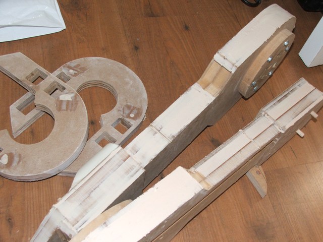
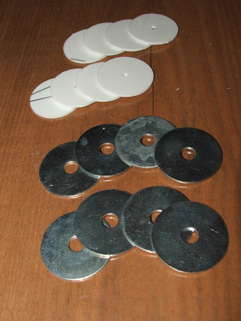
15th - 17th July 2009 I've started working with the legs during evenings this week - I aim to get R2 on his legs by next weekend before getting hold of some scooter motors to fit into the feet. Once he is standing I'll get back to reinforcing & finishing the feet. Lots of little bits done, like sanding the horseshoe edges, cutting a pair of ankle cylinder wedges for below the leg cylinders and mounting these with dowels - although they are not glued for the moment. Using dowels to mount the outer ankles and cutting and gluing four sections of MDF together to make the centre leg - its a bit rough but after a good sanding will look OK. I've also cut a hole out of each leg that the hub will sit in, and will use the cut-out as part of the leg to body shoulder along with a 160mm diameter MDF disc which will be bolted to the back of each leg, with some tee nuts hidden behind the horse-shoes. These will be secured to the frame with a few lengths of 12mm threaded rod that will pass from leg to leg through the centre of Artoo. Artoo's shoulder to body hub should be 170mm, or 6.6", and to make up the additional 10mm on the MDF discs I'll be using a 24mm section of 170mm diameter, 5mm walled tubing which I found in this sellers shop on eBay. Its very light and came in at an astounding £7 inc postage! The guy also sent me 4 bits of 25mm diameter, 5mm walled tubing, cut to 24mm, which when stuck to a 25mm washer, with a round headed bolt can be used as the shoulder buttons - so all in all, a nice eBay find. |
|
|
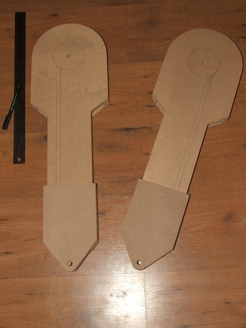
| 11th July 2009 When I ordered the frame, I also got an MDF legs kit from the same person. There was some damage to the legs during shipping, four of the horseshoes were broken, one wedge was damaged and the pivot on one leg is slightly scuffed - this can all be repaired during the sanding /filling process but its disapointing that the seller hasn't responded to my emails about this. Regardless, the legs have no channels for the wires that need to be dropped through to the feet, and the hub recess isn't cut out - so the only thing I've done with the legs is to mark out some areas for routing the wires which will be covered by the thruster housings and when I learnt to use a router, I router them out... |
|
|
| 4th July 2009 I've now glued the foot shells together ready to be reinforced with fibreglass. The centre foot is basically done bar the details, but I've left the outer feet with the sides and return off until get the foot motors and brackets. Looking at other build diaries, the motors will protrude into the battery boxes, and as I plan to have the battery box glued /fibre-glassed to the main foot shell with an access panel I though it best to leave them in this state for now until I know how the motors will fit. |
|
|
| 27th June 2009 More work on the foot shells, and the outer feet battery boxes. After looking at another R2 builders blog, I decided that his idea to use small diameter guttering was a much more effective way of making the curves on the outer feet that the battery boxes sit into. So, got myself a length (which is much more difficult than it sounds when you drive a MINI), and cut two sections that sit in the curve. I then drew where it met the front and back and cut it, and a section of 1mm styrene to fill the gap, with a craft knife. These are still not glued - yet.... The guttering also provided a nice easy way to make the top and bottom of the battery boxes, along with some end caps I found that are the correct dimensions for the overhangs at the front of each box. So, I marked up and cut some 2mm styrene for the sides, and glued them together with Super Glue to position them right - one dry a liberal coating of Araldite epoxy resin 2 part glue and they're stuck fast. These, and the coin returns, are the test for the feet, and now I'm happy with the glue, next job is to stick the feet together....
|
|
|
| 20th June 2009 I thought that the feet would be a good place to start, fairly easy and cheap to build. There are lots of very intricate plans for Artoo available at www.astromech.net so I printed off the feet plans and ordered some 2mm & 1mm styrene sheets from www.ema-models.com. The sheets are quite large and can easily be cut with a carft knife, or with scissors. Starting with the outer feet, I copied the plans onto a sheet of 2mm styrene, and then cut out all the bits with the knife, then did the same on a second sheet for the centre foot. I haven't glued them as yet, but test fitted the assemblies together with tape. The centre foot is more or less there apart from the detail, with the outer feet just missing the detail around the bottom, you'll notice the feet are almost triangular, but then turn back on themselves at the bottom - which I have done for the centre foot, but not yet for the outer feet. The feet have lots of small details on the side and slots on the turn-backs, these will be cut from 1mm styrene and glued on once the main foot shells are finished. They will be glued [after I have tested how good Araldite works with this styrene on some smaller details of the body], and then reinforced with fibreglass matting due to the wear and tear I expect them to get once finished. Once the shells are finished, I'll start on the detail. |
|
|
.JPG)
.JPG)
.JPG)
.JPG)
.JPG)
.JPG)
.JPG)
.JPG)
.JPG)
.JPG)
.JPG)
.JPG)
.JPG)
.JPG)
.JPG)
.JPG)
.JPG)
.JPG)
.JPG)
.JPG)
.JPG)
.JPG)
.JPG)
.JPG)
.JPG)
.JPG)

.JPG)
.JPG)
.JPG)
.JPG)
.JPG)
.JPG)
.JPG)
.JPG)
.JPG)
.JPG)
.JPG)
.JPG)
.JPG)
.JPG)
.JPG)
.jpg)
.jpg)
.JPG)
.JPG)
.JPG)
.JPG)
.JPG)
.JPG)
.JPG)
.JPG)
.JPG)
.JPG)
.JPG)
.JPG)
.JPG)
.JPG)
.JPG)
.JPG)
.JPG)
.JPG)
.JPG)
.JPG)
.JPG)
.JPG)
.JPG)
.JPG)
.JPG)
.JPG)
.JPG)
.JPG)
.JPG)
.JPG)
.JPG)
.JPG)
.JPG)
.JPG)
.JPG)
.JPG)
.JPG)
.JPG)
.JPG)
.JPG)
.JPG)
.JPG)
.JPG)
.JPG)
.JPG)
.JPG)
.JPG)
.JPG)
.JPG)
.JPG)
.JPG)
.JPG)
.JPG)
.JPG)
.JPG)
.JPG)
.JPG)
.JPG)
.JPG)
.JPG)
.JPG)
.JPG)
.JPG)
.JPG)
.JPG)
.JPG)
.JPG)
.JPG)
.JPG)
.JPG)
.JPG)
.JPG)
.JPG)
.JPG)
.JPG)
.JPG)

.JPG)
.JPG)
.JPG)
.JPG)
.JPG)
.JPG)
.JPG)
.JPG)
.JPG)
.JPG)
.JPG)
.JPG)
.JPG)
.JPG)
.JPG)
.JPG)
.JPG)
.JPG)
.JPG)
.JPG)
.JPG)
.JPG)
.JPG)
.JPG)