

|
|
|
|
13th December 2009 Its a bit of a pain to have to remove the rear door each time I want to switch Artoo on and off. Mounted to one of the coin returns on the rear is now a master power switch between the batteries and the main power board. When the switch is central it is all off, to the left switches the main electrics board on, and to the right isolates the main electronics and links the batteries to two small bolts, fixed to the underside of Artoo in the skirt area, which the battery charger can be connected to. |
|
|
|
6th December 2009 I removed the batteries that powered the lights in the head today, and soldered wires into the battery boxes for the positive and negative feeds. These are individually wired to a connector block and this 'harness' links each light to a single 4.5v power source fed up from the main electrics board. The power line is then linked to a small RC relay /switch so they can be switched on & off by the radio transmitter. I also took apart a USB card reader /MP3 player and hot glued it onto the electric board, again linked to a small RC relay so the sounds can be activated by remote - the speakers are quite small but I have a pair of old TV surround sound Sony speakers that will be fixed behind the main vents. |
|
|
|
29th November 2009 I think its getting close to the end of the build now - just down to finishing touches. The jobs remaining on the inner dome were to make the front holo-projector move using a spare RC channel, and to light the holos, again with another spare RC channel to turn them on and off. A small servo is now screwed and glued to the dome ring with a large paper clip opened up to attach it to tan eyelet on the bottom of the front holo-projector. This now moves side to side using the 3rd channel. Inside to light them I bought a pack of three small LED torches, cut the end off and soldered a couple of wires in place - sticking these into the holos with silicon. The lights will be wired to an RC relay, linked to a 4.5v power source wired up from the main board - the servo wire drops from a plastic eyelet secured to the coach bolt that is screwed through the dome at the centre top. |
|
|
|
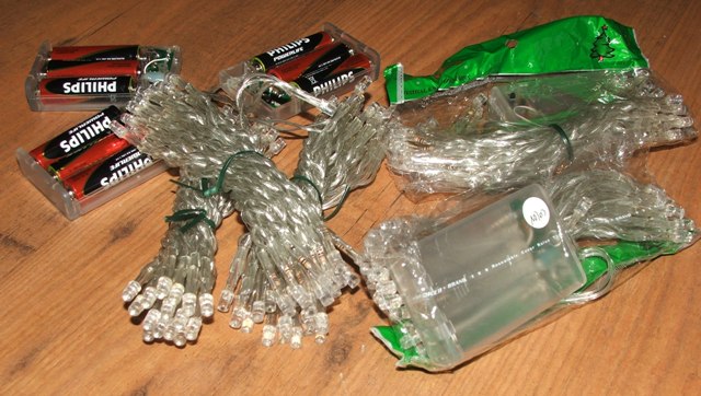
28th November 2009 Its been a busy week with work but I've managed to complete the logics and PSIs. I've made the rear logic and it's turned out much better than I planned.
I got 3 sets of multi coloured battery powered (4.5v) LED Xmas lights, 30 in
each string off eBay, and 2 more sets in blue and white. |
|
|
|
5th September 2009 We have dome rotation...! On the 3rd September I ordered an EMG30 12v motor, a bracket that this motor bolts to, a 100mm rubber tyred wheel and a SyRen 10A Regenerative Single Motor Driver all from Active Robots which arrived the next day by special delivery - great service. I started by bolting the motor driver to the chopping board using some 10mm spacers to allow cooling, which in turn was linked to the receiver using a servo extension cable. The motor and the bracket simply screw together, and the bracket is bolted to a length of L-profile steel, which is now bolted to the top ring of the frame - with a cut out in the frame so the wheel sits snugly against the bearing - making sure it was low enough to clear the dome, but high enough to clear the frame. Five packs of battery powered LED Christmas tree lights also arrived this week from a Chinese eBay seller - each with 30 bulbs per string. Three strings are multi-coloured to make the rear logic, and the other two are blue and white to make the front logics. |
|
|
|
31st August 2009 Quick electrical update today - I cut down the chopping board so it fits between the frame, and mounted it using four metal L-brackets and wing nuts onto fixed bolts. I also bolted some steel L-profile onto the base that the batteries now sit in. |
|
|
|
29th August 2009 Artoo is mobile, well he was today. I ordered a Sabertooth 2x25a speed controller yesterday and it arrived this morning, so the afternoon was spent cutting and trimming wires to link it to the batteries and motors in the feet - just a trial for now. It's all mounted on a polyester chopping board for now that will eventually be trimmed down to make a removable electrics board that will fix to either the inside front of Artoo, or one on of the side struts in the frame for easy access. Since the picture was taken the speed controller has been mounted using longer bolts with spacers between it and the board to help keep it cool. Of course I couldn't resist strapping everything inside Artoo for a test run... the noise is the belt slipping on the wheel which needs to be checked and most likely the axle moved back a quarter inch to tighten it up. |
|
|
|
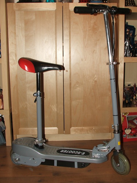
9th August 2009 Artoo is going to be full remote control, as in full forward, backward & turn /spin movement, with a head that spins and maybe the two arms in the body. First things first though, the feet motor brackets need to be made and attached to the legs, and the wires routed up through the leg. To get started I picked up a pair of electric scooters last weekend to strip down for the motor, wheels, batteries and general wiring to be retro-fixed into Artoo's feet and a sheet of 1mm steel. Starting by removing the wheel and motor from the scooter, I used some card to make a template which I transferred to the steel and cut out a pair of each of the three sides, and four L-shaped sections for the top to fix the leg to. I also had to remove the brake hub from each wheel which were held in place by four aluminium rivets which were easily drilled out. |
|
|
| After test fitting the motor and wheel onto the frame, I welded the three sections together, and added a section of 6mm aluminium tube, with some 4mm threaded rod at the lower corner nearest the motor to add some strength to the lower edge. Once this was cooled, I re-test fitted the motor and wheel just to be sure it all still lined up. |
|
|
| The L-brackets on the top are just bolted in place, and each has a 8mm hole drilled through the middle that the leg will mount to - each with a captive nut, welded in place to make bolting the leg on more straight forward. I've also cut a 1" length of 10mm aluminium tube that will be glued into the hole on each leg so that the bolt doesn't damage the wood near the ankle - and the feet brackets are a perfect fit onto the ankles. |
|
|
|
Artoo on his [back] feet for the first time.... |
|
|
.JPG)
.JPG)
.JPG)
.JPG)
.JPG)
.JPG)
.JPG)
.JPG)
.JPG)
.JPG)
.JPG)
.JPG)
.JPG)
.JPG)
.JPG)
.JPG)
.JPG)
.JPG)
.JPG)
.JPG)
.JPG)
.JPG)
.JPG)
.JPG)
.JPG)
.JPG)
.JPG)
.JPG)
.JPG)
.JPG)
.JPG)
.JPG)
.JPG)
.JPG)
.JPG)
.JPG)
.JPG)
.JPG)
.JPG)
.JPG)
.JPG)
.JPG)
.JPG)
.JPG)
.JPG)
.JPG)
.JPG)
.JPG)
.JPG)
.JPG)
.JPG)
.JPG)
.JPG)
.JPG)
.JPG)
.JPG)